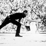
The Second World War generated a big crisis in all aspects: economic, social, human values, etc., and artists were the first to react. Art needed a change and the “action painting” or “happening” was used to express the artist’s feelings, starting from zero and literally attacking traditional painting that embodied conventional art. Jackson Pollock was the first artist who started taking distance from the painting and, without being conscious, art entered into a new era. Following his example, many other artists wanted to express themselves in a different way breaking with conventional art.
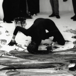
In such a way, new generation artists did not consider themselves as painters nor as sculptors, but rather they saw themselves as simple artists for whom any theme or material could be art. Happenings, performances and conceptualism finished with thinking painting as a representation and as an artistic object, granting a privilege to the process that happens on the back of an art work, the ideas that generate art and its performance aspects.
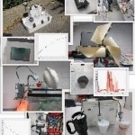
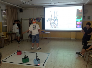
After going with my advanced students in the fall of 2012 to an exhibition of Pollock’s legacy at Miró’s Foundation Museum in Barcelona, called “Explosion!”, the students had the idea to use robots to make an ephemeral virtual painting were the robots’ behavior is controlled by algorithms that create the art work. A Microsoft Kinect sensor allows a student to interact with his/her own body on the same virtual painting, and different image recognition algorithms are used for the interaction between the students’ body digital drawing and the one made by the robots. In addition, each robot is provided with an Android camera that allows the recognition of each other, and shows the public the same scene that each robot sees, but under its own perspective. A computer controls the dynamic generation of the painting and manages the robots’ behavior when they see each other or when they reach the end of the field (or virtual painting).
The Kinect sensor and program

The Kinect sensor developed by Microsoft has a built in RGB camera, a depth sensor and a multi-array microphone, which provide full-body 3D motion capture, facial recognition and voice recognition capabilities. The students used the Kinect to make their bodies interact with the robots and with the virtual painting. To program the Kinect, initially they started with MIT’s Scratch using Stephen Howell’s development, but to be able to interact with the robots they had to switch to LabVIEW and adapt the University of Leeds Kinesthesia Toolkit (developed for kinesthesia purposes, to help patients to recover the mobility of some parts of the body), do some research, and a little bit of reverse engineering.
The following video shows a “work in progress” presentation and performance that BOGATECH competition team students did on June 2013 at Icària High School, Barcelona.
The program has two different sections: the program control and the visualization. Program control determines what parts of the skeleton are shown (joints and bones), the colors used, the thicknesses and what we call the “persistence” of the skeleton (meaning the history of the skeleton or for how long it is shown in the digital picture). The visualization section shows the skeleton according to the changes made by the program control and the video recorded by the Kinect (only used for control purposes in this project). In addition, it shows in real time the digitally modified videos recorded by the Android cameras and the virtual painting produced by both the robots and the Kinect.

The Kinect program has 4 different phases executed sequentially:
- Kinect initialization
- Reading the data captured by the Kinect
- Processing and interpreting the data to create the skeleton (program main case structure in the image below)
- Finalizing the program by closing the Kinect connection
Phases 2 and 3 are inside a loop that repeats until the user stops the program or an error occurs.

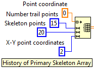
The most interesting feature the students developed was to add to the matrix of the skeleton – which is composed of coordinates, points (elements with 3 coordinates X, Y and Z, although in 2D we only use X and Y) and 20 joints (or skeleton points) – with 20 bones (or connections between 2 joints or skeleton points, managed separately in the render VI), creating a history of the skeleton to be able to show and control the display of its “trail”. This is shown graphically in the visualization image above and in the initialization of the skeleton array in the image below, with a default trail of 15 skeletons that can be changed even dynamically during the performance.
Android cameras and video visualization program
The Android cameras show the path of the robot and different color filters applied to each image inspired by Andy Warhol paintings that allow identifying each robot. In the future the students will use the cameras themselves to identify the robots by their color and react to each other in different ways. To connect the cameras to LabVIEW the project uses DroidCamX and sends the video via Bluetooth.
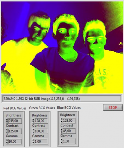
To capture the Android cameras video streaming, the project uses 3 DroidCamX Android Apps specially compiled for the project to capture independently the 3 videos and send them via Bluetooth to the same PC using 3 different incoming video sources. It also uses 3 companion applications in the PC to convert the 3 Bluetooth videos received into 3 USB independent signals for LabVIEW to recognize them easily with the Vision Acquisition module and Express VI. Finally, as the above program image on the right shows, the RGB video colors are manipulated and the image is turned 90 degrees. This process is dynamically done 3 times, one for each robot Android camera.
Robot construction

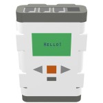
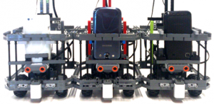
The robots are built with LEGO Technic pieces, designed with LEGO Digital Designer and composed of one MINDSTORMS NXT intelligent brick, 2 motors to drive the robot, 1 light to indicate the change of algorithms dynamically and 3 sensors, one light sensor to detect the limits of the filed, one ultrasonic sensor to avoid collisions between robots and one compass sensor to calculate the rotation angle of the robot. This version of the project calculates the position of each robot using its rotation angle and the distance moved using the motors’ number of rotations. Finally the robots have a special support for the Android phones and they are covered by a paper color skin to identify them.
Main robot program
As you can see in the image below, the LabVIEW main robot program has a specific sequential data flow and it is organized by sub-VIs that are used by all the robots with different parameters.
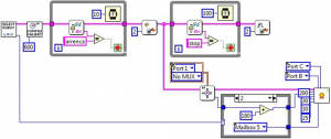
The main robot program has 2 different phases. The first phase has 3 steps where the user has to select the robot, then the compass sensor auto-calibrates and finally the robot waits for the message from the computer to start (shown in the first loop). The second phase has two different steps that run in parallel, represented by splitting the NXT reference data wire in purple. The program sets a flag and enters a loop to wait for the computer to send a message to stop the program. At the same time, it sets the initial position of the robot by reading the compass sensor, it sets its parameters and calls the robot main algorithm that controls its behavior.
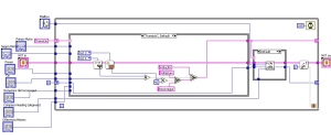
In the robot behavior main algorithm (image above) we can see 3 different steps. First we can see the “transition” state (and the rest of the case structure states) where the “state machine” program takes the decisions of what actions to do next by reading the sensors. Next the robot sends its present position to the computer (shown in the second case structure) and finally, it checks the flag in case it has to exit the loop to stop the program.
Robots control main computer program
The robots control computer program is responsible to set up the default initial parameters, to synchronize the performance robots’ start, to send them instructions of what algorithms to use when they see each other during the performance and finally to send them a message to stop (which is not yet implemented in the version of the program shown below).

As the above image shows, the program uses a frame sequence to ensure that every step is finished by all the three robots before entering to the next step. In addition, the Bluetooth connection is established by the host computer for security and to avoid losing time in the stage at the beginning of the performance. Finally, we can observe that the display of the virtual painting uses an array with all the features and attributes of the three robots, ensuring code efficiency and readability. In addition, the array makes also easier if you want in the future to add more robots with minimum program changes.
Final computer program combining everything together
The final computer program combines all the different technologies of the project. It communicates with the three robots and sends them instructions via Bluetooth, it controls the Kinect sensor via USB and visualizes the three Android cameras of each robot using the vision control, which it is capable of recognizing colors.

As the above image shows, the final main computer program has three different phases:
- The initialization phase is composed of three sequence frames to establish the Bluetooth connection with the robots, to wait for the user to start the performance by clicking a button in the program user interface and to initialize an array with all the different and specific parameters of each robot to start the virtual painting.
- The general loop phase that combines dynamically during the whole performance the robots painting with the Kinect drawing and displays the video of the 3 Android cameras.
- The program finalization phase which sends a stop message to the robots and closes the Kinect connection.
Problems encountered
The biggest problem that the project encountered is related to the Bluetooth connection which is not very reliable and it is too slow. We had 7 devices connected: one computer, 3 robots and 3 Android cameras. The Bluetooth connection between the robots and the computer is a little bit unstable and MINDSTORMS NXT only allows connecting 3 robots to one host computer. In addition, some of the coordinates that the robots dynamically send to the computer during the performance are lost, due to the lack of speed of the connection. This implies that the “virtual” path of the robots is not very precise and accumulates errors during the performance. To manage the Bluetooth connection between the computer and the robots it is very important to time correctly all the loops to ensure that all the messages are read. Finally, the videos look a little bit choppy due to the lack of Bluetooth connection speed, but we like very much the effect of sequences of almost still images!
The solution is to use WiFi instead of Bluetooth, but to present such a project to the RoboCup Junior competition, first the International Committee has to approve the use of this protocol. In relation to the NXT there are some third party sensors that provide WiFi connection and for the EV3, it is already supported. This will allow much faster, stable and reliable connections, not only between the robots and the computer, but also for the video streaming using IP video cameras. In addition, it will be possible to use many more robots for a more spectacular performance in the “virtual painting” as well as in the real field, which could be much bigger.
Future work
There are several aspects that could be improved. One line of research can be to make the computer recognize the virtual line intersections between the robots and the Kinect. This will allow the human to interact with the robots changing their behavior and trajectory.
Another improvement can be to implement the color recognition of the images streamed by the Android cameras. This will allow the robots to recognize each other and react accordingly modifying their behavior when they meet on the field.
In addition, each robot could use a “fiducial” code (that you can design yourself) which will enable the host computer, using an additional simple USB camera, to use pattern and image recognition software to identify and paint the robots’ trajectory on the virtual painting with a much bigger precision. Students have already tested this new strategy which is very promising, although it needs to add into the scene a new camera with a special support connected to the host computer.
It could be also interesting to add more sensors to the robots for the human to interact with the robots on the real field.
To design a more interesting performance, the robots need more different behavior algorithms, that the students did not have enough time to design and that can be very easily added to the robot’s state machine programming style.
Finally, to take full advantage of all the improvements, an attractive choreography needs to be designed. In addition, if there is time, maybe the robots could play different musical chords that might change and synchronize according to the different behavior algorithms.
Latest posts by Josep Fargas (see all)
- Write Better Code with Design Patterns in EV3 - 14 February 2019
- How to Toggle a Motor On/Off With a Touch Sensor - 16 November 2017
- How to Wait for More than One Sensor Condition - 19 October 2017
- To light or not to light - 7 July 2016
- From Sequential Programming to State Machines - 14 April 2015

