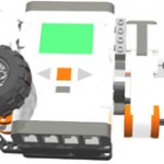
TETRIX is a robotics building system that was created by Pitsco. The system consists of aluminium elements for construction and powerful drive motors, controlled by an NXT brick. This article provides building instructions and programming examples for a simple TETRIX robot.
Here are three Sample TETRIX VIs for TETRIX projects.
Building instructions
Place the plate on top of the channels. There should be four small holes in the plate that line up with four small holes in each channel. Take the DC Motor Controller from your kit and line it up with two of the four holes that line up on one side of your robot. Fasten the controller, plate, and channel together with a screw and nut. Feed the screw down through the top and attach a nut on the bottom. Use the hex key to tighten fully.
Also attach the servo controller to the base in the same way on the other side.
Motors
Take a DC motor, a motor mount, a motor shaft hub and a wheel from your kit. Slide the motor mount around the front of the motor until the leading edge of the motor mount is flush with the crack in the motor housing, as seen in the picture. This may take a bit of force as the motor mount is designed to fit snugly.
Once you have the motor mount on the motor, attach the shaft hub by sliding it onto the axle and tightening the screw into the flat part of the axle.
Attach the wheel to the motor axle mount with two screws. Now repeat this procedure with another motor, motor mount, motor shaft hub, and wheel, so that you have two wheels that are ready to be mounted to the base of your robot.
Take the two motors and attach them to the underside of the base, using the long motor mount screws. Secure them the outermost holes on the channels, making the motors as far apart as possible so that you will be able to attach the motor cables later.
Front wheel
Take from your kit a short tube, two tube clamps, and two tube plugs. Place one plug in one end of the tube and attach a clamp to the end. Make sure that the plug stays at the end of the tube and doesn’t wander to the middle.
With the other plug and clamp, Repeat this procedure on the opposite end of the tube, making sure that the new clamp lines up with the existing one along the tube.
Attach a hard-point connector to an L bracket as seen here with a small screw and nut.
Take another L-bracket, a long stand-off post, and the servo joint pivot bracket from the kit, along with the tube assembly and the L bracket you just created. Connect them according to the picture, making sure to use only the stand-off post and a screw when connecting the L bracket with the hard-point connector to the pivot bracket.
Attach an axle hub to one omni-wheel with two screws through the small holes in the center of the wheel. Then attach the other omni-wheel to the other side of the hub, so the two wheels sandwich the hub. Make sure that the small, black, outer wheels on the omni-wheel are staggered, so that only one touches the ground at a time.
Now take your complete tube assembly, the two omni-wheels, two bronze bushings, and two large axle spacers, as well as one axle.
Place the components between the two arms of the joint bracket on the tube assembly in the following order: bushing, spacer, wheels, spacer, bushing. Feed an axle through all of these components and through the two large holes on the joint bracket.
Tighten the screw on the axle hub to keep the axle in place.
Mount the omni-wheel assembly onto the base of the robot by placing the L bracket on top of the plate and screwing it into the two center-most holes.
Next, create this battery-securing apparatus by placing two screws through two hard-point connectors and one flat bracket and into two long stand-off posts.
This apparatus should fit snugly over the battery pack.
Place the battery pack with the flattest side up on the robot base and secure it to the top plate by placing the posts over the pack and screwing them through the plate.
Attach two 5×3 LEGO angular beams to the hard-point connectors with connector pegs. Then connect a 7-hole beam to the outside of each of the angular beams, and connect the NXT to the top hole of the beam, so that it hangs comfortably on top of the robot.
Also attach a touch sensor to the hard-point connector on the front of the robot using connection pegs and another 7-hole beam.
Now connect the wiring of the robot. First, connect the motor controller and the touch sensor to ports 1 and 2 on the NXT. Next, connect the motor power cables to the motor 1 and motor 2 ports on the motor controller and then to the DC motors. Then connect the On/Off switch to the battery port of the motor controller and connect the battery pack to the On/Off switch with the white plug.
The last thing you should do to complete your robot is take all the wires and put them somewhere out of the way. This can be done by tying them down, wrapping them around other parts, or just bundling them together.
Programming instructions
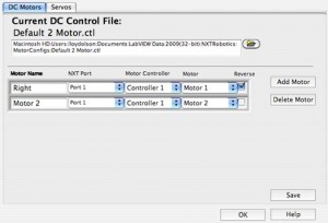
To start programming your TETRIX robot, open LabVIEW and choose to open a blank VI targeted to the NXT. Then go to Tools > NXT Tools > TETRIX Motor Configurator. This is where you tell the NXT where the motors are on the TETRIX robot. Click on Add Motor, so that you now have two motors configured. Then look at the drop down menus. If the motor controller is connected to port 1, you should choose port 1 in the NXT Port drop-down. Since only 1 motor controller is connected, the motors are connected to motor controller 1. For the Motor drop-down, change one of them to Motor 2. Then rename the motors, so that you know which one is which. A common naming scheme would be to name them Right and Left. Also, since your motors are facing opposite directions, you can reverse one of them so that they are both oriented the same way. Here is a sample motor configuration.
Once you have the motors configured, you can program the TETRIX robot just as you would any other LEGO NXT robot. The only difference is that instead of stringing in “Port 1” or some other port, you would use the Motor Configurations icon under the TETRIX tab in the Functions Palette. There are several sample exercises on the next page that can be used as introductory programming tutorials on the TETRIX robot.
Exercise 1: Drive forward for 5 seconds, then stop.
Note: These sample programs are available for download at the bottom of this page.
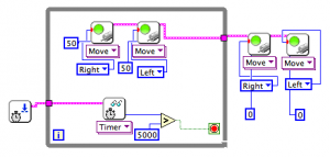
For this exercise, there are three parts to your program. The motors need to turn off, they need to stay on for a while, and then they need to stop. To turn the motors on, use two Move DC Motors blocks to turn on the motors and motor configuration constants to specify which motors. Be sure to specify what power level to give the motors. The one unique part about programming with TETRIX is that the motors need to be constantly fed inputs. If they do not receive a new command in 2.5 seconds, they will stop. To avoid this, you will need to put them in a loop, so that the program constantly feeds them inputs. To stop the motors, simply use two more Move DC Motors blocks and wire in a power level of 0. The final code should look something like this:
Remember that this motor configuration has the right motor reversed. If the right motor was not reversed, the motors would need power levels of opposite sign to drive straight because they are oriented in opposite directions.
Exercise 2: Drive forward until bumped, then back up and stop.
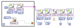
This exercise should look very similar to the first one. Instead of exiting the loop at a certain time, though, this program will wait for a touch (specifically for the touch sensor to be pressed). Therefore the Read Timer icon needs to be changed Read Touch > Pressed. Then you will need to wire in which port the touch sensor is connected to. Once the sensor is pressed, the motors should move backwards, so you will need two Move DC Motor blocks and two motor configuration constants, except this time you should feed them a power level less than zero. Add another a Wait For Time block, but do not have the robot go backwards for more than 2.5 seconds or they will time out. Then stop the motors as you did in Exercise 1, and your code should look like this:
Exercise 3: Drive forward with speed proportional to the reading of the sound sensor. Stop when bumped.
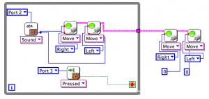
This program will once again look similar to the first. There should a loop constantly telling the motors to move forward, but instead of constants wired in to the power level, place a Read Sensor block set to the sound sensor and connect the output terminal of the Read Sound Sensor block to the power level terminals of the motor block. The code should look like this:
Sample program downloads
CEEO
Latest posts by CEEO (see all)
- Chair for Mr Bear - 21 August 2020
- Assistive Technology: Making Lives Easier - 20 August 2020
- Sturdy Tower - 14 June 2020
- Going the Distance - 21 May 2020
- GPS accuracy testing with LEGO bricks - 10 September 2015


